


What Causes Slag Buildup on Steel Ladles?
During operation, severe slag buildup or skull formation can occur on the inner walls of steel ladles. As the number of heats increases, the buildup layer becomes progressively thicker.
Slag buildup reduces the ladle's effective capacity and increases its empty weight, making it easy to reach or exceed the overhead crane's maximum lifting capacity and creating potential safety hazards during crane operation. It can also obstruct the smooth addition of alloying materials and ladle filler sand, adversely affecting stable and continuous production.
When severely affected ladles are cleaned, the castable around the ladle rim may be damaged, shortening the ladle campaign life and increasing refractory consumption and the cost per ton of steel. In addition, because the buildup layer varies in thickness and location, it becomes difficult to accurately assess the remaining thickness of the ladle lining. In severe cases, inaccurate assessments can result in steel penetration and breakout.
Steel ladles are generally constructed using monolithic castable linings, with alumina-magnesia castables serving as the working lining. During the initial stage of service, new ladles typically do not experience significant slag buildup. The problem usually begins after approximately five heats, with excessive buildup reaching its peak after 30–40 heats.
After repeated use, cracks develop in the castable lining, allowing molten steel and slag to penetrate the refractory. This results in a sandwich-like structure consisting of alternating layers of castable, frozen steel, castable, and frozen steel.
Overweight ladles not only develop thick buildup layers but also suffer from severe slag accumulation around the ladle rim. The buildup often contains frozen steel, which makes the deposits containing high-melting-point phases more compact and resistant to removal. The frozen steel also acts as an anchor, firmly bonding the buildup layer to the lining.
Therefore, cracking of the castable lining and the adhesion of frozen steel are the primary causes of severe slag buildup in steel ladles.
1. Causes of Castable Cracking
During service, fused magnesia reacts with fused alumina in the matrix to form spinel. This reaction results in approximately 8% volume expansion, which can cause cracking in the castable lining.
Once cracks develop, the lining's resistance to slag penetration decreases, promoting slag infiltration and subsequent buildup during operation.
2. Analysis of Frozen Steel Adhesion Poor thermal insulation of the steel ladle
At present, carbonized rice husks are used as the primary insulating cover material. However, carbonized rice husks have poor spreading properties. After being added to the ladle, they tend to accumulate in piles rather than spreading rapidly and evenly across the molten steel surface.
As a result, some areas of the molten steel remain exposed to the atmosphere, increasing heat transfer and preventing the insulating material from performing effectively.
Furthermore, carbonized rice husks provide inadequate thermal insulation. Although they are produced by carbonizing rice husks and are used as a heat-generating material, their relatively low calorific value and short reaction duration limit their heating effect. The covering layer also fails to form an effective thermal barrier, resulting in substantial heat loss from the molten steel.
During the middle and later stages of casting, the surface covering can be observed turning red, indicating that the carbonized rice husks are being consumed rapidly. Consequently, the slag layer inside the ladle becomes exposed to cooling, forming a solidified slag cap that adheres to the ladle wall.
Measures to Prevent Slag Buildup in Steel Ladles
1. Improve the slag resistance of the ladle castable
For slags with relatively high FeO content, the cement content in the castable can be appropriately increased. The CaO in the cement reacts with alumina powder to form CA₆ (calcium hexaluminate). A phase assemblage consisting of MA (magnesium aluminate spinel), CA₆, and A (alumina) can develop a network-like structure.
This structure helps reduce the volume expansion associated with spinel formation, thereby mitigating cracking in monolithic ladle linings and preventing slag buildup.
Meanwhile, increasing the addition of fine magnesia powder improves the castable's resistance to slag corrosion but reduces its resistance to slag penetration. Considering the balance between these two properties, the fine magnesia content in the original castable formulation was reduced from 6% to 4%.
An online rapid ladle preheating system was also installed downstream of the steelmaking furnace. The rapid preheater can raise the ladle temperature to 900°C within five minutes, reducing the temperature drop of the molten steel and thereby helping to minimize slag and frozen-steel buildup.
2. Improve thermal insulation by fitting ladle covers
All ladles used on the continuous casting machine were equipped with insulating covers. The ladle cover was connected to the ladle through a flexible hook arrangement, allowing both to move together and ensuring that the cover remained integrated with the ladle during handling.
Whenever a ladle carrying molten steel was transported to the continuous casting machine, the cover was placed over the ladle to provide thermal insulation, as shown in Figure 1.
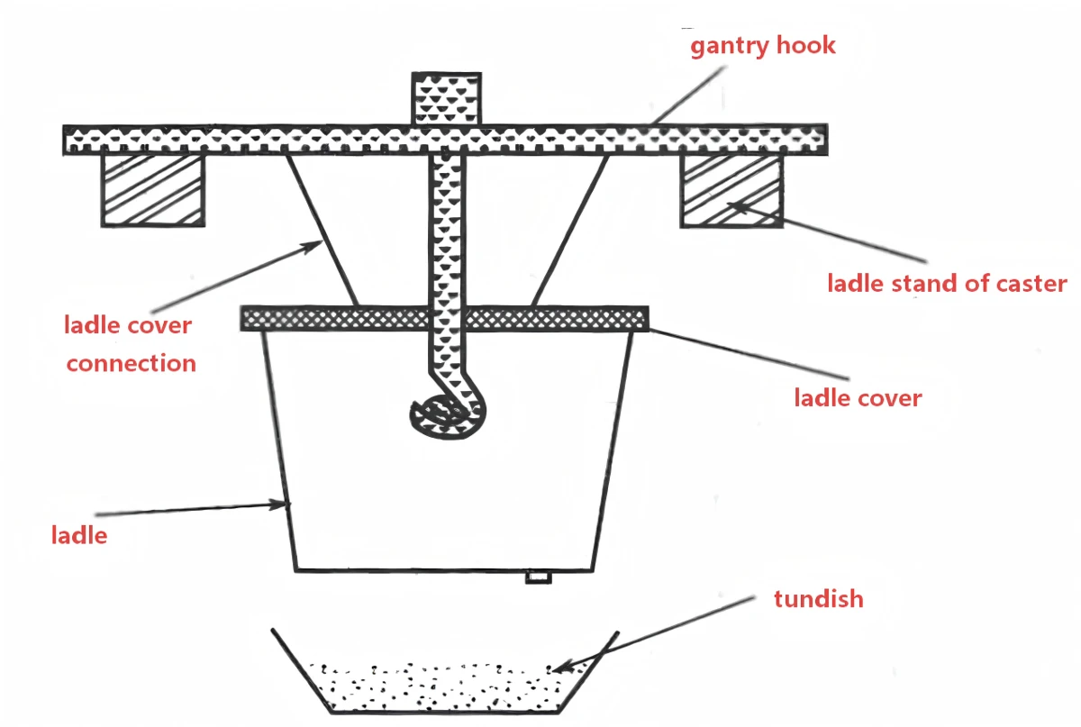
Figure 1. Schematic Diagram of Thermal Insulation Using a Steel Ladle Cover
(3) Use an Online Rapid Ladle Preheater After the Steelmaking Furnace to Increase the Temperature of Empty Ladles
An online rapid ladle preheater is installed downstream of the steelmaking furnace. The preheater can raise the ladle temperature to 900°C within five minutes, reducing the temperature drop of the molten steel and thereby minimizing slag and frozen-steel buildup.
This measure shortens the ladle turnaround time and reduces the proportion of cold ladles.
By upgrading the continuous casting machine for higher operating efficiency, better coordination between the steelmaking furnace and the continuous casting machine can be achieved. This reduces the number of ladles required for online operation and consequently shortens the ladle turnaround cycle.
What Refractory-Related Factors Affect the Service Life of Refining Ladles?
(1) Effect of Ladle Brick Material
In the early stages of ladle furnace operation, conventional high-alumina bricks and alumina-magnesia bricks were used as ladle refractories. These bricks exhibited rapid corrosion, which began at the slag line. As corrosion progressed, the slag line moved downward and quickly extended into the molten-steel bath area below it, eventually causing steel breakout at the slag line and damage to the entire ladle, resulting in scrapping.
After the ladle brick material was changed to magnesia-carbon (Mg-C) bricks or magnesia-alumina-carbon (MAC) bricks, corrosion of the working lining in the molten-steel bath area slowed significantly, and downward movement of the slag line was reduced. After approximately 20 uses, the slag line had moved down only slightly. However, severe corrosion still occurred at the slag line.
Analysis indicated that the slag-line area was particularly vulnerable to arc radiation and erosion caused by the movement of molten steel and slag in the upper region. These conditions increased the likelihood of refractory spalling, making the service life of the slag-line lining unstable.
After the introduction of improved tar-bonded magnesia-carbon bricks at the slag line and optimization of slag fluidity, the service life of the slag-line lining became nearly synchronized with that of the working lining in the molten-steel bath area.
(2) Effect of Ladle Lining Installation Quality
Monitoring of ladle operation revealed that areas where severe flame leakage occurred through brick joints during ladle preheating were also the areas where joint erosion was most severe during service. These locations were also more susceptible to steel penetration and breakout through the joints.
This was primarily attributed to excessively wide brick joints, which allowed molten steel and slag to penetrate and attack the refractory lining.
(3) Effect of Porous Plugs on Ladle Service Life
① Effect of porous plug material
In the initial stage, alumina-based porous plugs were used. Due to their poor quality, the plugs frequently became clogged or completely blocked, making replacement necessary. This increased the risk of steel leakage around the porous plug assembly and shortened the service life of the ladle.
② Effect of porous plug installation position
When the porous plug was installed too close to the ladle wall, the molten-steel flow generated during argon blowing severely scoured the lining near the plug. This accelerated refractory erosion and reduced ladle service life.
(4) Effect of Electric Arc Radiation on Ladle Service Life
While waiting for refining after tapping from the primary steelmaking furnace, carbonized rice husks were generally added to preserve heat. The carbonized rice husks could agglomerate with the slag.
During the initial stage of refining, the electric arc was sometimes exposed and not adequately covered by slag. As a result, high-temperature arc radiation directly heated the ladle wall, causing localized overheating and refractory damage.
Human and Operational Factors Affecting Refining Ladle Service Life
(1) Effect of Improper Ladle Operation and Management
① Effect of new-ladle preheating on service life
The service life of the ladle lining is closely related to the quality of preheating before the first use.
Because magnesia-carbon or magnesia-alumina-carbon bricks are used, inadequate preheating causes the lining temperature to rise rapidly during operation. Large amounts of gas, including water vapor and gases generated by tar decomposition, are released rapidly, resulting in severe erosion at the brick joints.
This is also a major reason why deep pits and cavities develop along the joints of the ladle lining.
② Effect of tapping into a cold ladle or washing the ladle with molten steel
When molten steel is tapped into a cold ladle, the lining experiences severe thermal shock caused by rapid heating and cooling, accelerating refractory erosion.
At the same time, tapping into a cold ladle results in a greater temperature drop in the molten steel and extends the refining time, further aggravating erosion of the lining, particularly at the slag line.
When ladle turnover becomes difficult and there is insufficient time for preheating, or when preheating is inadequate, molten steel may be used to heat or wash the ladle. This practice can cause ladle bricks to crack or spall, adversely affecting service life.
③ Effect of improper argon blowing
Gas leakage at argon supply pipe connections, poor porous plug performance, or a mismatch between argon flow rate and electrical power can result in a large temperature difference between the upper and lower regions of the molten steel.
Consequently, temperatures become excessively high at the slag line and in the upper bath area, accelerating refractory erosion in these regions.
(2) Effect of Improper Tapping from the Primary Steelmaking Furnace
① Effect of unstable tapping weight
When the tapping weight fluctuates significantly, refractory erosion in areas other than the slag line can become severe. This is particularly problematic when the tapping weight is low, because the slag line may move downward into the working surface of the molten-steel bath area, further shortening ladle service life.
② Effect of unstable tapping temperature
Tapping at a low temperature extends the refining time and has a greater adverse effect on ladle service life.
③ Effect of slag carryover during tapping
Frequent slag carryover from the primary steelmaking furnace introduces highly oxidizing slag into the ladle. This slag reacts with the refractory lining, particularly at the slag line, forming low-melting-point compounds and causing the reaction layer to deteriorate.
In addition, excessive oxidizing slag prolongs the refining process, resulting in severe erosion of the lining, especially at the slag line.
How to Improve Ladle Campaign Life in LF Refining Through Better Refractory Installation
(1) Improvements to Ladle Lining Practices
① Optimization of refractory materials
The working lining in the molten-steel bath area of refining ladles should use magnesia-carbon bricks or high-quality magnesia-alumina-carbon bricks.
The slag-line lining should use premium-grade magnesia-carbon bricks containing an appropriate amount of antioxidants.
Approximately 10 high-quality magnesia-carbon bricks should also be installed in the first and second courses on the slag-discharge side. The gap between the permanent lining and the working lining should be filled tightly with several millimeters of magnesia sand.
② Improvement of lining installation quality
The installation quality of the working lining must be improved, with the following requirements:
Brick joints should be less than 1 mm wide.
The height difference between bricks in the same course should not exceed 1.5 mm.
Brick joints in adjacent courses must be staggered.
The porous plug should be positioned at an appropriate location toward the center of the refining ladle.
The joints between the bottom bricks and the porous plug should be less than 2 mm wide to reduce molten-steel erosion of the lining near the plug.
(2) Improvements to Ladle Bottom Installation
When steel is tapped through an eccentric bottom outlet, the molten steel directly impacts the ladle bottom. The thickness and quality of the refractory bricks in the impact zone can therefore be increased.
In one improvement, the Mg-C bricks in the impact zone were made 50 mm higher than those in the surrounding area, and their quality grade was upgraded to 18A. These measures effectively improved the service life of the ladle bottom.
Previously, intermediate ladle repairs mainly involved replacing the nozzle seat bricks and porous plug seat bricks, while the entire ladle bottom was not replaced. The area around the seat bricks was repaired by pouring alumina-magnesia spinel castable.
After five to six heats, deep pits tended to develop in the refining ladle bottom. Wet patching was therefore necessary; otherwise, severe molten-steel contamination could occur, increasing the inclusion content in the steel.
Under the improved intermediate-repair procedure, the amount of castable used is minimized. After the castable is poured into the repair area, it is compacted with a vibrating rod. This approach has produced satisfactory results.
Leveling and filling around the ladle nozzle seat bricks and porous plug seat bricks must strictly comply with the relevant technical operating procedures.
The brine concentration must be maintained above 1.3 mol/L to ensure proper sintering of the magnesia powder. Otherwise, vibration and rotation of the ladle during service may cause unsintered magnesia powder to flow out through the joints, leaving voids. Under the substantial static pressure of the molten steel, these voids can lead to cracks in the ladle bottom and ultimately cause steel penetration and breakout.
How to Improve Ladle Structure to Extend LF Refining Ladle Campaign Life
(1) Addition of a Thermal Insulation Layer
To improve the thermal insulation performance of the ladle, an insulation layer, typically an insulating board, was added between the permanent lining and the steel shell.
Under normal conditions, the reported molten-steel temperature drop during casting decreased from 1°C/min to 4°C/min.
With a cover installed on the tundish, temperature fluctuations during the early and later stages of tundish operation could be maintained within a range of 12°C.
This technology addressed the poor thermal insulation of the permanent lining, enabling lower tapping temperatures, shorter refining times, reduced power consumption, and less erosion of the Mg-C working lining by high-temperature molten steel.
(2) Improvement of the Ladle Permanent Lining
Because refining times are long and refining ladles operate under harsh conditions, their campaign lives are often relatively short.
The permanent lining was therefore changed from a refractory-brick construction to a monolithic cast structure.
Previously, the permanent lining was constructed using thin clay bricks bonded with high-alumina refractory mortar. A major drawback of this method was the risk of steel leakage when molten steel penetrated the joints of the Mg-C working lining.
After improvement, the permanent lining was formed in a single casting using alumina-magnesia spinel castable. The resulting inner surface was smooth, free of voids, and resistant to material displacement. No spalling occurred after air drying and preheating.
This modification fundamentally controlled ladle leakage caused by steel penetration through working-lining joints, extended ladle campaign life, improved operational safety, and supported stable production.
(3) Treatment of the Joint Between Old and New Refractory Bricks During Intermediate Ladle Repairs
During intermediate ladle repairs, a step of approximately 20–60 mm commonly formed at the joint between the newly installed and existing magnesia-carbon bricks.
If left untreated, the molten steel flowing over this step under argon stirring could form vortices, creating a weak point in the lining.
Therefore, after replacing the slag-line bricks during intermediate repairs, the step was leveled and tightly filled with magnesia-carbon ramming or jointing material containing resin (see Figure 2).
Because the composition of this material is similar to that of magnesia-carbon bricks and the resin provides good bonding strength, the problem can largely be resolved.
This approach is particularly effective when the ladle is in the middle or later stages of its campaign, or under abnormal operating conditions such as severe slag-line erosion or steel leakage. Its benefits become even more pronounced when the remaining slag-line lining thickness has decreased to approximately 80–100 mm.
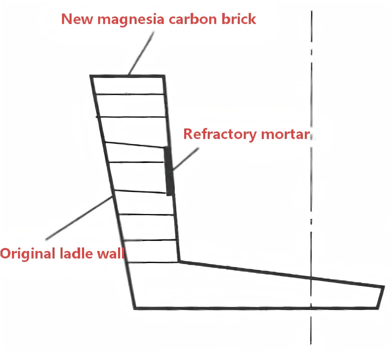
Figure 2. Treatment of the Step Between New and Existing Refractory Bricks During Intermediate Ladle Repair
(4) Improving the Quality of Refractory Jointing Material
Magnesia-carbon (Mg-C) jointing material is used for bricklaying. Since its main chemical composition and physical and chemical properties are essentially the same as those of magnesia-carbon bricks, it helps resolve the following problems:
Steel leakage through brick joints: It effectively prevents molten steel from penetrating through the joints.
Erosion at brick joints: It reduces erosion of the ladle lining at the joints.
Difficult ladle dismantling and poor lining surface quality: Because this material does not bond to the permanent lining (alumina-magnesia spinel), it significantly reduces the labor intensity of ladle dismantling while maintaining a smooth inner surface of the permanent lining. This provides a solid foundation for improving ladle relining quality.
Application of the Jointing Material
During service, cracks, holes, and other defects often develop in steel ladles. These defects can be effectively repaired by pouring Mg-C jointing slurry into the affected areas after the ladle has cooled.
This approach significantly improves the previously weak areas. No problems were observed after one complete ladle campaign, and the results were substantially better than those achieved using magnesia powder mixed with brine for ladle repairs.
How to Improve LF Refining Ladle Campaign Life Through Better Operating Practices
(1) Properly Schedule the Turnover of New and Used Ladles
As a key link connecting steelmaking and continuous casting, the refining ladle plays a critical role in maintaining smooth production. Production disruptions can also adversely affect ladle campaign life.
For example, during production incidents, a ladle may remain in the refining position for up to approximately 10 hours, including the waiting period before refining. Therefore, the use of older ladles must be carefully scheduled and managed.
Furthermore, because coordination among the EAF–LF–continuous casting process is not always optimal, the first refining heat may require a longer refining time and a higher molten-steel temperature. Consequently, older ladles should, whenever possible, be avoided for the first heat. This practice helps extend ladle service life and reduce operational incidents.
(2) Strengthen Operational Control at the Furnace
Potentially harmful operating conditions must be effectively controlled to avoid the following situations:
1. Oxidizing slag entering the ladle: Oxidizing slag carried over into the ladle interferes with refining, making it difficult to establish a reducing atmosphere quickly and severely corroding the ladle slag line.
2. Excessive use of fluorite to adjust slag fluidity: Fluorite should not be added excessively to improve refining slag fluidity. If the slag becomes too fluid, it can cause severe erosion of the slag-line lining.
3. Excessive tapping weight: Excessive steel tapping weight makes refining more difficult and may result in insufficient slag volume. It also directly affects slag-line service life. The combined effects of bottom argon stirring, electric arc radiation, and molten-steel buoyancy act directly on the uppermost three courses of ladle bricks, causing the slag-line bricks to loosen, deteriorate, and eventually spall. This can lead to premature ladle withdrawal and serious operational consequences.
4. Incorrect positioning of a heavy ladle at the refining station: When a heavy ladle is placed at the refining position, it must be properly centered. Otherwise, electric arc radiation can cause severe damage to the ladle. The area around Electrode No. 2 is also a high-temperature zone where operational incidents are more likely to occur.