


Purge plugs serve as critical functional components for the bottom argon blowing process in ladle secondary refining. With metallurgical functions of homogenizing and purifying molten steel, purge plugs work in two ways. On one hand, stirring by injected argon gas homogenizes the temperature and composition of molten steel at different positions inside the ladle. On the other hand, following the vacuum pump principle, argon bubble surfaces adsorb fine non-metallic inclusions such as Al₂O₃, SiO₂ and MA, while harmful gases including nitrogen, hydrogen and oxygen in molten steel are sucked into the bubbles. As bubbles rise, they gradually coalesce and grow, and are finally captured by the slag layer. Therefore, purge plugs are indispensable key refractories for clean steel smelting, and their service performance directly affects the purity of molten steel. Besides, the service life of purge plugs is one of the bottlenecks restricting the minor repair life of ladles. Stable service life of purge plugs is a prerequisite to guarantee smooth ladle production. To this end, this paper briefly reviews the material upgrading and structural evolution of ladle purge plugs, analyzes the structural characteristics and metallurgical performance of three types of composite purge plugs: dispersed type, core-plate type and ceramic tube type, and focuses on elaborating the damage mechanism of composite purge plugs.
1. Structural Evolution of Purge Plugs
1.1 Single-structure Purge Plugs
Dispersed purge plugs were first developed in the 1960s. Adopting the inverse particle close-packing theory, they use a large amount of equal-size particles together with ablatable materials to prefabricate numerous non-directional connected pores. The brick body is formed by hydraulic or vibration pressing. Restricted by the forming method, its height generally cannot exceed 270 mm. High-alumina or magnesia dispersed purge plugs suffer poor erosion resistance and height limitation, failing to meet service life requirements. Straight through-hole purge plugs emerged in the 1980s. Several stainless steel tubes with a diameter of 1–3 mm were embedded inside the brick, which was fabricated by casting. Their service life is longer than that of dispersed ones. In the 1990s, following the trend of monolithic refractories, ultra-fine powder and high-efficiency dispersants were introduced. Low-cement chrome-corundum castables exhibited superior properties. The application of straight through-hole purge plugs in bottom-blown argon ladles gradually declined, and they were eventually replaced by slit-type purge plugs made of corundum-spinel or chrome-corundum castables. Slits are formed after high-temperature ablation of polyester films with a thickness of 0.15–0.25 mm.
Purge plugs with single gas channel structures including dispersed type, straight through-hole type and slit type (schematic diagrams shown in Figure 1) can hardly adapt to various smelting conditions universally. Especially traditional dispersed and straight through-hole types have been phased out from the ladle purge plug market. In practical application, single-structure purge plugs often present inherent drawbacks that are difficult to overcome. High-temperature fired slit-type purge plugs have poor thermal shock resistance. Thermal stress concentrates within 50 mm from the working surface. Under frequent thermal cycling shocks, longitudinal and transverse cracks tend to generate. Molten steel penetrates into slits and cross-sections, resulting in reduced gas flow or even gas blockage. Traditional dispersed purge plugs have low density, poor resistance to molten steel scouring and oxygen cleaning, and short service life. Moreover, safety alarm devices cannot be designed for integrally formed traditional dispersed bricks.
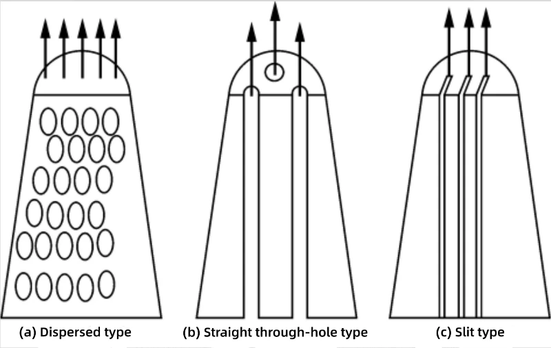
Figure 1 Schematic diagram of single‑structure purge plugs
1.2 Composite-structure Purge Plugs
Composite gas channel structures enable purge plugs of different structures to complement each other's strengths and avoid weaknesses. Several commercially mature composite-structure purge plugs available on the market can be divided into three categories according to their primary gas channel structures: dispersed type, core-plate type and ceramic tube type. Diversified market demands drive the evolution from single-structure purge plugs toward composite structures. Dispersed composite purge plugs are widely favored by steel plants in Japan, South Korea, Vietnam and other countries; core-plate composite purge plugs are commonly adopted by steel plants in Europe, the United States and the Middle East; ceramic-tube composite purge plugs are well received by steel plants in Russia and other regions.
All three types of composite-structure purge plugs possess service properties incomparable to those of single-structure purge plugs:
1) The bubbles generated by dispersed composite purge plugs are finer than those from slit-type purge plugs. Under the same gas flow rate, more bubbles are produced, which greatly increases the collision probability with non-metallic inclusions and harmful gases. This improves the efficiency of adsorbing fine inclusions and capturing harmful gases, making it the preferred solution for smelting high-quality clean steel.
2) Energy-releasing gaps exist between assembled plate-like core plates, and the corundum-mullite material features low thermal expansion rate. These characteristics endow core-plate purge plugs with excellent thermal shock resistance, thus avoiding the fatal defect of transverse cracking and molten steel penetration encountered in high-temperature fired slit-type purge plugs, and guaranteeing a high gas permeability rate of the purge plug.
3) Ceramic-tube composite purge plugs combine the high-flow characteristic of slits and small-sized bubbles from straight micro-pores.
The oxygen cleaning intensity and frequency required for the three composite purge plugs are much lower than those for conventional high-temperature fired slit-type purge plugs. Oxygen cleaning involves harsh working conditions for operators with heavy fume and severe environmental pollution. With rising labor costs and growing environmental awareness, their advantages of light firing and non-firing become increasingly prominent. For the gas permeability rate and service life of purge plugs, oxygen cleaning acts as a double-edged sword. Purging with an oxygen lance can restore the gas permeability of the purge plug, yet it inevitably damages the brick body and causes excessive erosion of the purge plug.
Ranking of oxygen cleaning resistance for different purge plug types: conventional high-temperature fired slit-type purge plugs > ceramic-tube composite purge plugs > core-plate composite purge plugs > dispersed composite purge plugs. Conversely, the ranking of oxygen cleaning necessity, intensity and frequency: conventional high-temperature fired slit-type purge plugs < ceramic-tube composite purge plugs < core-plate composite purge plugs < dispersed composite purge plugs. Naturally, cleaning can be omitted if the purge plug self-recovers its permeability before the next smelting cycle and the gas flow reaches the set value.
The design of composite-structure purge plugs shall follow the principle of functional zoning, developing strengths and avoiding weaknesses, and complementary advantages. Gas channel composite structures can be realized in both longitudinal and transverse directions:
1) Longitudinal direction: divided by different functions, the working layer and safety layer of the purge plug perform separate duties. The working layer focuses on thermal shock resistance, corrosion resistance and scouring resistance. The safety layer prioritizes high-temperature identifiability and sufficient gas flow supply. The cast body provides structural support and fixes the gas permeable elements. Optimal gas channel structures and refractory materials are selected for different positions to maximize essential functions without excessive redundant design for secondary functions. This fundamentally resolves the problem of partial performance surplus and partial performance deficiency of single-structure purge plugs.
2) Transverse direction: multiple gas channel structures can be adopted within the working layer of the purge plug to comprehensively consider bottom blowing flow rate, bubble quantity, bubble diameter and anti-penetration performance.
Figure 2 shows schematic diagrams of various composite-structure purge plugs. More gas channel combinations can be derived according to service life and performance requirements. As illustrated in Figure 2, slits are added to the working layers of dispersed and ceramic-tube types to compensate for insufficient flow capacity of dispersed and ceramic tube gas permeable elements. However, differences in the quantity and layout of slits lead to varying contributions of slits to the total gas flow.

Figure 2 Schematic diagrams of composite-structure purge plugs
2. Damage Mechanism of Composite‑structure Purge Plugs
2.1 Dispersed Composite‑structure Purge Plugs
Dispersed composite-structure purge plugs generally adopt the Al₂O₃-SiO₂-Cr₂O₃-ZrO₂ system. Tabular alumina and white fused alumina particles (<1 mm) are selected as aggregates. The matrix mostly consists of Al₂O₃ micropowder, Cr₂O₃ micropowder, fine ZrO₂ powder or zircon fine powder. Common binders include aluminium dihydrogen phosphate, polyvinyl alcohol, aluminium-silica sol and so on. They are shaped by isostatic pressing, hydraulic pressing or vibration pressing, followed by high-temperature sintering above 1650 ℃.
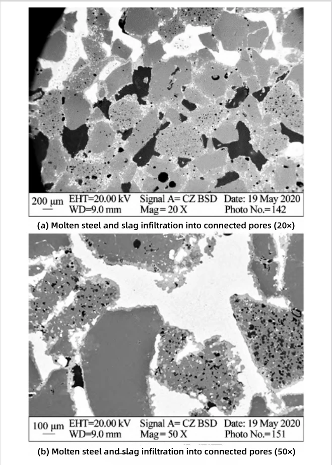
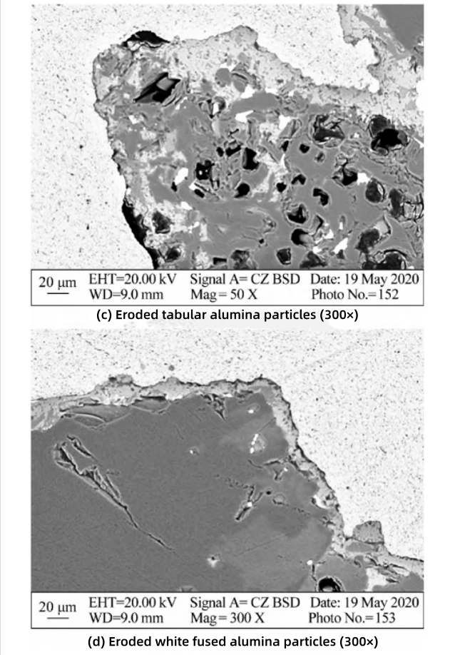
Figure 3 SEM micrographs of residual dispersed purge plug
Figure 3 shows the SEM micrographs of residual dispersed purge plug. It can be seen that molten steel and slag preferentially invade pores with larger diameters. The slag reacts with the surface of alumina grains. In terms of reactivity, tabular alumina has finer grains and more grain boundaries compared with white fused alumina. Therefore, the reaction between slag and tabular alumina is more intensive than that with white fused alumina, as shown in Figure 3(c) and Figure 3(d). Obviously, the dominant damage mechanism of dispersed purge plugs is the infiltration of molten steel and slag into connected pores, rather than the erosion of the matrix.
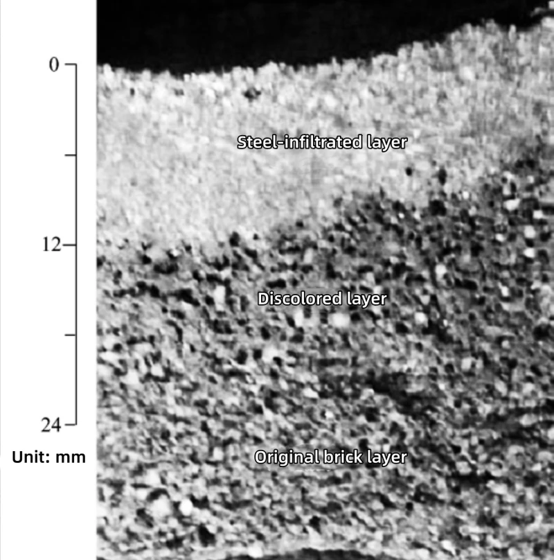
Figure 4 Photograph of residual dispersed purge plug
Figure 4 shows the digital photograph of residual dispersed purge plug taken from a 300 t refining ladle in a domestic steel plant. The steel-infiltrated layer locates at a depth of 0–12 mm from the working surface; the connected pores are blocked by steel and become completely impermeable. The discolored layer is at a depth of 12–18 mm from the working surface. After each heat casting, the ladle is transferred to the hot repair station for natural gas back-blowing. Since the steel-infiltrated layer prevents natural gas from contacting air, the natural gas cannot combust and cracks at high temperature to form a black carbon deposition layer. Therefore, the steel-infiltrated layer must be removed by high-pressure scouring and oxygen lance ablation in each campaign to guarantee back-blowing for the next campaign. Optimizing the particle size grading to reduce the proportion of large-diameter connected pores and narrow the pore size distribution range, improving the resistance of dispersed bricks against molten steel and slag wetting and infiltration to minimize the thickness of steel-infiltrated layer, and lowering the frequency of oxygen lance cleaning are effective approaches to extend the service life of dispersed composite purge plugs.
2.2 Core-plate Composite-structure Purge Plugs
Figure 5 presents the SEM micrographs of used residual core-plate purge plug from a steel plant. The EDS analysis results of each point and each layer in Figure 5 are listed in Table 1.

Figure 5 SEM micrographs of residual core-plate purge plug
Note: M - Mullite; TA - Iron-aluminum spinel; C - Low-melting-point Al-Fe-Si-Ca phase
| Item | Al2O3 | SiO2 | Fe2O3 | CaO | Cr2O3 | Na2O |
|---|---|---|---|---|---|---|
| Point 1 | 16.05 | - | 83.43 | - | 0.52 | - |
| Point 2 | 72.14 | 8.11 | 17.06 | 2.69 | - | - |
| Reaction layer | 45.47 | 6.19 | 44.48 | 3.86 | - | - |
| Original brick layer | 83.95 | 14.36 | 1.13 | - | - | 0.56 |
Table 1 EDS analysis of each point and each layer in Fig.5(b) and Fig.5(c)
It can be seen from Fig.5(a) and Fig.5(b) that the main material of the core plate is corundum-mullite. The aggregates are mainly tabular alumina and fine sintered mullite particles (≤1 mm). Due to the mismatch in thermal expansion coefficients between the two types of particles, microcracks form around them. The matrix adopts Al₂O₃ micropowder and SiO₂ micropowder. After high-temperature firing, mullite formed by in-situ reaction in the matrix acts as the binding phase to connect corundum and mullite particles.
As shown in Fig.5(c) and Table 1, the bright regions (strip-shaped and dot-shaped) are iron-aluminum spinel generated by the reaction between fine white fused alumina particles (0.5–1 mm, 0.1–0.5 mm) and molten steel (see Point 1). The grey regions are low-melting-point Al-Fe-Si-Ca phases formed by the reaction of fine mullite particles and mullite matrix binding phase with molten steel and CaO in slag (see Point 2). Such phases can be easily removed by oxygen cleaning during hot repair.
Conventional corundum-mullite core plates tend to form low-melting-point phases with CaO in steel slag. Cr₂O₃ and ZrO₂ can be incorporated into the core plate to enhance its resistance to molten steel and slag corrosion and reduce slag infiltration and erosion. Alternatively, silicon-free materials such as high-purity chrome corundum and high-purity corundum-spinel can be adopted. Without deteriorating high-temperature mechanical properties and thermal shock resistance, introducing no SiO₂ into the core plate can improve its slag corrosion resistance.
2.3 Ceramic-tube Composite Purge Plugs
The ceramic tube has a diameter of approximately 15–25 mm and contains dozens of straight through micropores with a diameter of 0.3–0.5 mm. The SEM micrographs of the ceramic-tube purge plug are shown in Fig.6.
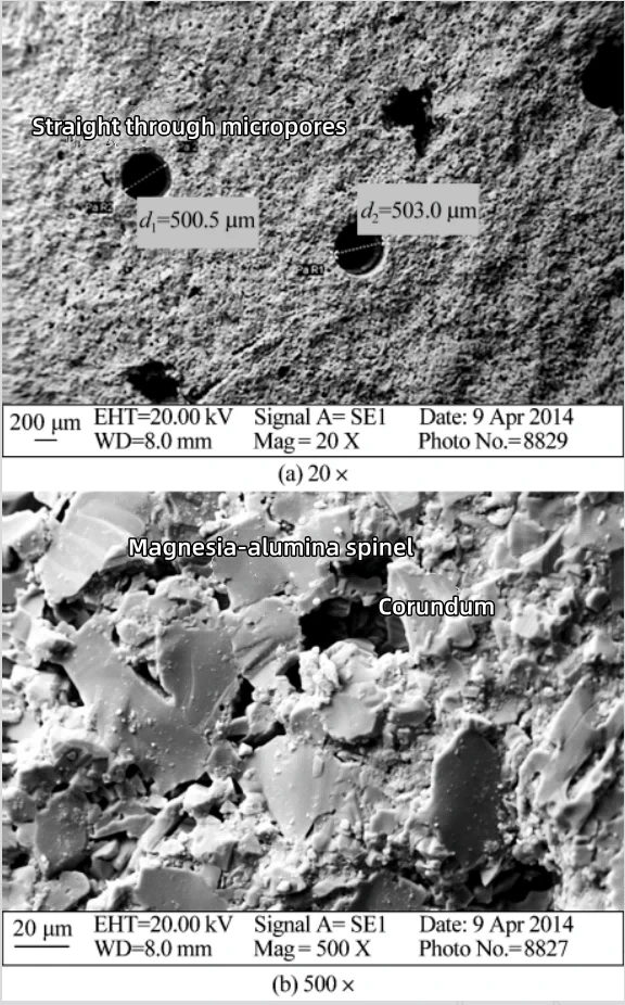
Figure 6 SEM micrographs of ceramic-tube purge plug
It can be seen from Fig.6 that the micropores have high circularity with a diameter of 0.5 mm. The main material of the ceramic tube is corundum-spinel. Tabular alumina and pre-synthesized spinel are selected as raw materials, together with a small amount of plasticizers such as soft clay and organic binders. The mixture is extruded, cured, dried and sintered at high temperature, with a small amount of liquid phase existing in the matrix.
Figure 7 shows the photograph of residual ceramic-tube purge plug from an 180 t ladle of an overseas steel plant. It can be observed that the surface of the purge plug is relatively smooth without residual steel or slag. It can be inferred that transverse fracture occurred on the purge plug body, and four ceramic tubes were broken. The ceramic tubes appear black. When natural gas back-blowing is performed, fracture of the purge plug interrupts the gas passage. The back-blown natural gas cannot come into contact with oxygen injected from the oxygen lance. Natural gas cracks at high temperature to form carbon residue, which leads to the black colour.
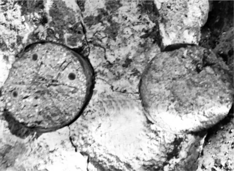
Figure 7 Photograph of residual ceramic-tube purge plug
Therefore, improving the thermal shock resistance of the ceramic-tube purge plug body is the key to solving its damage. In addition, if the molten steel has low viscosity, it will infiltrate into the straight through micropores under static pressure. When the infiltration depth is large, the molten steel solidifies, and the solidified steel can hardly be blown out during back-blowing. If the resistance of pore walls against molten steel wetting can be improved, or the pore diameter can be further reduced to below 0.2 mm, the problem of steel infiltration in straight through micropores is expected to be solved.
3. Conclusions
The gas channel structure of purge plugs determines their gas permeability characteristics, and further affects the metallurgical performance and service life. Regardless of the structural type, the key points in production and application lie in the formation and maintenance of gas channels (pores, ducts, slits). Apart from material quality, the service performance of purge plugs is also closely related to the gas channel manufacturing process and operation process.
For purge plugs with different composite structures, their damage mechanisms and improvement measures are summarized as follows:
(1) Purge plugs of various composite types differ in gas channel structure and material composition, resulting in distinct damage mechanisms. For dispersed composite purge plugs, molten steel and slag infiltrate and block the connected pores, and the steel-infiltrated layer suffers scouring ablation or oxygen lance burning erosion - this is their primary damage mechanism. For core-plate composite purge plugs, CaO in steel slag reacts with the mullite binding phase in the core-plate matrix to form low-melting-point Al-Fe-Si-Ca phases, which are gradually eroded under oxygen lance scouring; this is the main damage mechanism. For ceramic-tube composite purge plugs, the cast body slit region has poor thermal shock resistance. Frequent thermal shocks cause transverse fracture of the brick body, or steel infiltration occurs in straight through micropores, leading to bottom blowing failure or reduced gas flow rate. These constitute the main damage mechanism for ceramic-tube composite purge plugs.
(2) Optimization of macro and microstructural design and material innovation are approaches to extend the service life of composite purge plugs. Optimizing particle size grading and improving the resistance to wetting and infiltration of molten steel and slag are effective ways to prolong the service life of dispersed composite purge plugs. Incorporating Cr₂O₃ and ZrO₂ into the core plate can improve the core plate's resistance to wetting by molten steel and slag and reduce slag erosion. Improving the thermal shock resistance of the cast body of ceramic-tube purge plugs, reducing the diameter of straight through micropores, and ensuring volume stability of straight through micropores at high temperatures represent the development direction for this type of purge plug.