


A torpedo ladle is one of the main transportation carriers for hot metal turnover between the current ironmaking and steelmaking processes. It features large capacity, low temperature drop, and long heat preservation time, creating more favorable conditions for long-distance hot metal transportation and energy consumption reduction in converters. With the increasing smelting costs of steel enterprises, the consumption of scrap steel is no longer limited to the converter steelmaking process. Instead, high-temperature hot metal is used to melt scrap steel to improve the utilization rate of scrap steel in the steel smelting process. The erosion and melting loss of the inner lining refractories in the torpedo ladle are intensified after adding scrap steel. This paper analyzes and discusses the causes of serious melting loss of the inner lining refractories after introducing the process of adding scrap steel to the torpedo ladle.\
Service Overview
On February 27, 2018, the No.25 torpedo ladle was put into operation with a tare weight of 253.56t. On November 6, 2018, after 500 heats of service, it was taken out of service for the first cold inspection, with a tare weight of 254.24t. It was baked on November 14 and put back into use on November 18. On March 27, 2019, after 804 heats of service, it was taken out of service for the second cold inspection, with a tare weight of 253t. The cold inspection showed normal conditions and no slag accumulation in the ladle. However, it was stopped due to temperature measurement alarm at the 808th heat. During the cold inspection after being taken out of service, local pits were found in the cone area. The working layer bricks in the pitted area were melted to the permanent layer, and the residual thickness of the working layer bricks in the non-melted edge area was 210mm (original brick thickness 287mm).
The positions and areas of the pits are as follows:
① 19-26 rings on the R side cone of the non-chassis position, 5-10 bricks per ring, with an area of about 0.6m²;
② 20-26 rings on the R side cone of the chassis position, 4-9 bricks per ring, with an area of about 0.5m². But after 4 heats of use, the working layer bricks in the local cone area were melted to the permanent layer.
Influence Analysis
The chemical compositions of blast furnace slag and residual slag on the surface of refractories during the use of No.25 torpedo ladle were analyzed by X-ray fluorescence spectrometer (XRF). The microstructure and phase composition of the residual bricks at the concave parts in the torpedo ladle were observed and analyzed by scanning electron microscope (SEM), energy dispersive spectrometer (EDS) and diffractometer. Meanwhile, the slag resistance test of Al-Si-C bricks in the residual slag was carried out according to GB/T8931-2007 *Test Method for Slag Resistance of Refractories.
2.1 Analysis of Slag Composition
(1) The residual slag at the concave erosion part of the working lining of No.25 torpedo ladle was taken for chemical analysis of slag composition, and the results are shown in Table 1.
| Component | Fe₂O₃ | SiO₂ | Al₂O₃ | MnO | TiO₂ | CaO |
|---|---|---|---|---|---|---|
| Content | 42.814 6 | 20.306 3 | 12.995 7 | 10.737 4 | 4.747 8 | 4.208 3 |
| Component | MgO | ZrO₂ | K₂O | SiO | Cr₂O₃ | |
| Content | 2.897 6 | 0.583 5 | 0.310 2 | 0.254 4 | 0.144 2 |
Table 1. Composition of residual iron slag / %
By comparing the chemical compositions of the slags in Table 1 and Table 2, it is found that oxides such as MnO, ZrO₂, and Cr₂O₃ appear in the slag inside the torpedo ladle, which are quite different from those of blast furnace slag. It is judged that these three types of oxides remain in the slag layer on the surface of the working lining bricks after the scrap steel added externally to the torpedo ladle is melted.
2.2 Analysis of Residual Bricks
2.2.1 Analysis of Slag Penetration
Take the residual bricks from the depressed area. Use a scanning electron microscope (SEM) to observe the microstructures of the slag layer, deteriorated layer, and original brick layer of the residual bricks (as shown in Figures 1–9). Meanwhile, use an energy dispersive spectrometer (EDS) to analyze the phases of the residues.

Figure 1 Micrograph of slag penetration in residual bricks at the depressed part
It can be seen from Figure 1 that under the microscope, the eroded working lining brick has an obvious sense of hierarchy. From the slag layer to the original brick direction, according to the differences in state and composition, it can be divided into four regions (1, 2, 3, 4). The composition analysis is shown in Table 3.
| Detection Area | Position | Na₂O | MgO | Al₂O₃ | SiO₂ | K₂O | CaO | TiO₂ | MnO | Fe₂O₃ |
|---|---|---|---|---|---|---|---|---|---|---|
| Area 1 | Porous Top Slag | 0.55 | 4.01 | 25.17 | 49.27 | 0.40 | 6.37 | 5.90 | 6.39 | 1.95 |
| Area 2 | Less - Porous Top Slag | - | 3.81 | 26.39 | 50.92 | 0.27 | 6.19 | 5.34 | 5.35 | 1.73 |
| Area 3 | Deteriorated Transition | 0.40 | 1.69 | 40.73 | 44.62 | 0.34 | 4.26 | 2.73 | 2.51 | 2.72 |
| Area 4 | Original Brick Layer | - | 0.54 | 62.47 | 34.18 | - | 0.26 | 1.42 | - | 1.39 |
Table 3 Chemical compositions of different regions (in %)
By comparing Table 3 with Table 1 and Table 2, it is found that the content of MnO gradually decreases with the erosion depth of the slag on the brick until reaching the original brick layer. The penetration and erosion of MnO accompany the entire erosion process of the molten slag. Meanwhile, the content of SiO₂ in Regions 1, 2, and 3 is significantly higher than that in the iron slag and blast furnace slag. It is judged that at high temperatures, MnO undergoes reduction and oxidation reactions with SiC and C in the brick lining refractories successively, generating SiO₂ and a small amount of gas.
It can be seen from Table 3 that approximately equal amounts of SiO₂ exist in both Region 1 and Region 2. It can be observed that there are more pores in Region 1, while there are relatively fewer pores in Region 2. It indicates that the reaction products in the top slag layer of Region 1 are mainly anorthite, which is in the form of CaO at high temperatures. However, the contents of K₂O and Na₂O in Region 1 are higher than those in Region 2. By comparing the microstructures of Regions 1 and 2 in Figure 2, two completely different morphologies are presented. The glassy phase has high viscosity, and the degree of crystallization after cooling is low, forming a porous structure; the reaction products in the near-slag layer of Region 2 are mainly gehlenite, which has a high melting point and low viscosity at high temperatures, and the degree of crystallization after cooling is high, with fewer pores (see Figure 3).

Figure 2 Enlarged view of the slag penetration areas (1, 2)

Figure 3 Enlarged view of Slag Penetration Area 2

Figure 4 Micrograph of the aggregate in Area 2 penetrated by molten slag
2.2.2 Analysis of Aggregate Erosion
Using a scanning electron microscope (SEM) under microscopic conditions, the effect of molten slag on bauxite aggregates in the refractory material of the working lining brick after slag penetration was observed. As shown in Figure 4, the erosion of bauxite aggregates in the near-slag layer is quite special, basically divided into a porous region 5 and a low-porosity region 6. Figure 5 shows that in the low-porosity region 5, the bauxite is mainly composed of corundum, mullite, and glassy phase. The slag erosion manifests as preferential erosion of the glassy phase, forming a liquid phase that wraps around corundum and mullite grains.

Figure 5 Enlarged view of the porous area 5 of the aggregate

Figure 6 Enlarged view of the low-porosity area 6 of the aggregate
From Figure 6, it can be observed that the bauxite in the low-porosity area 6 is relatively dense. The original pore structure of the raw material has a direct impact on the slag resistance. Considering the premise that the composition of the bauxite particles should be relatively uniform, the chemical composition results of areas 5 and 6 (as shown in Table 4) show that the erosion of bauxite aggregates by slag is dominated by the penetration of CaO and MnO, while TiO₂ in the bauxite migrates to the slag first.
| Detection | Position | MgO | Al₂O₃ | SiO₂ | CaO | TiO₂ | MnO | Fe₂O₃ |
|---|---|---|---|---|---|---|---|---|
| Area 5 | Porous Bauxite | 0.82 | 77.68 | 15.21 | 2.18 | 1.86 | 1.04 | 1.22 |
| Area 6 | Low - Porosity Bauxite | 0.40 | 79.98 | 14.41 | 0.86 | 2.67 | 0.40 | 1.28 |
Table 4 Chemical Compositions of Different Regions / %
2.2.3 Analysis of Matrix Erosion
As shown in Figures 7 and 8, in the transition layer region, the matrix region has become integrated with the molten slag, seemingly a process of dissolution of matrix components into the molten slag. As shown in Figure 9, the interface between the original brick layer and the transition layer is very clear, indicating that the presence of graphite plays a crucial role in preventing the penetration of molten slag. When the graphite is oxidized and removed, pores are formed, and the molten slag then starts and completes the penetration of the matrix and aggregates. This indicates that the erosion and dissolution process of the molten slag on the brick matrix starts from the intrusion pores, forms a glassy phase, and finally wraps around the corundum and mullite grains.

Figure 7 Transition Layer Region 3

Figure 8. Enlarged view of the boxed area
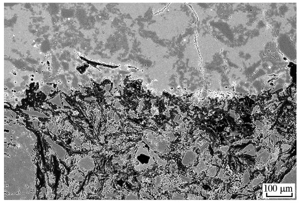
Figure 9 Interface between transition layer and original brick layer of residual brick
Conclusion
(1) The composition of the residual slag in the No. 25 torpedo ladle differs significantly from that of the blast furnace slag, especially with a higher MnO content.
(2) The scanning electron microscope (SEM) analysis results of the residual bricks show that MnO, CaO, etc., cause significant melting loss to the aggregates and matrix of the aluminum silicon carbide carbon bricks. In summary, it can be seen that the pit formation in the cone of the No. 25 torpedo ladle is related to the huge changes in the local slag and iron composition in the ladle during its operation, which leads to rapid melting loss of the aluminum silicon carbide carbon bricks and results in local pit formation.